Disponibile Prodotto più richiesto
HC-M-HS 200/40-MOD-ST-PE
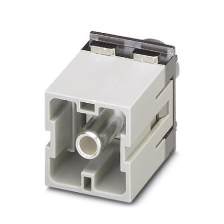
HC-M-HS 200/40-MOD-ST-PE 1637184 PHOENIX CONTACT Contact insert module
$0.00USD
4949 in magazzino
Specifiche chiave
Codice GTIN:4046356095235
Nota:Made to Order (non-returnable)
Chiave d'ordine:1637184
Pagina del catalogo:Page 551 (C-4-2015)
Informazioni fornitore
Prodotti: 0
Di solito spedito entro 2-3 giorni lavorativi
Qualità garantita
Spedizione veloce
Supporto tecnico
Specifiche tecniche
| Parametro | Valore |
|---|---|
| Codice GTIN | 4046356095235 |
| Nota | Made to Order (non-returnable) |
| Chiave d'ordine | 1637184 |
| Pagina del catalogo | Page 551 (C-4-2015) |
| Unità di imballaggio | 1 pc |
| Paese di origine | DE (Germany) |
| Numero tariffario doganale | 85366990 |
| (Condizioni ambientali) | 16 mm (70 mm²) |
| Quantità minima d'ordine | 100 pc |
| Materiale di contatto (generale) | Copper alloy |
| Corrente nominale (Dimensioni) | 200 A |
| Larghezza (dati commerciali chiave) | 34.2 mm |
| Altezza (dati commerciali chiave) | 54.5 mm |
| Lunghezza (dati commerciali chiave) | 29.4 mm |
| Profilo di collegamento (Dimensioni) | PE |
| Materiale portante del contatto (generale) | PC |
| Materiale della superficie di contatto (generale) | Ag |
| Serie (Caratteristiche meccaniche) | HC-M-HS |
| Peso per pezzo (imballaggio escluso) | 98.500 g |
| Presa esagonale (condizioni ambientali) | WAF 5 |
| Coppia di serraggio (condizioni ambientali) | 8 Nm (25 mm² ... 35 mm²) |
| Collegamento (Caratteristiche meccaniche) | Note on axial connection technology:Only for stranded wires. The specified conductor cross sections refer to the geometric cross section of the cable used.Use of cables with a geometric cross section that differs greatly from the nominal cross section of the cable should be checked before use.The wiring space for axial screw technology is designed for fine strand cables according to VDE 0295 Class 5. Deviating cable structures (e.g., Class 6 cables) should be checked before use.Assembly instructionsBefore assembly, ensure that the tapered screw is turned back all the way (chamber is open). The cables must not be twisted. The wires should be inserted as far as they will go into the contact chamber (until the insulation touches the contact). Hold the wires in position and use the socket wrench to tighten. The used wire end should be cut off before connecting again. The connection screw may only be retightened once to prevent the litz wires from breaking. To prevent damage to the contact, the wire/cable should be mechanically intercepted at an appropriate distance from the connection point (e.g., by using a plate cutout). DIN VDE 0100-520:2003-06 contains information on how to do this correctly. The module cannot be used simultaneously with HC-B..-TMB-SD-IP65 and HC-B..-TMS-SD-IP65 protective covers.PE mounting plateThe PE plate must be pressed hard against the swing frame using the 4 screws. First loosen the 4 screws of the PE plate and then tighten them again once the module is fixed in the swing frame. |
| Altezza minima dell'alloggiamento (condizioni ambientali) | 72 mm |
| Sezione trasversale del conduttore (condizioni ambientali) | 25 mm² ... 40 mm² (The cross section specification refers to the geometric cross section of the cable used) |
| Metodo di collegamento (Caratteristiche meccaniche) | Axial screw connection |
| Collegamento secondo la norma (dati sui materiali) | UL |
| Cicli di inserimento/estrazione (condizioni ambientali) | ≥ 500 |
| Sezione trasversale di collegamento AWG (condizioni ambientali) | 3 ... 2 |
| Istruzioni di montaggio (Caratteristiche meccaniche) | - Use only flexible conductors,- Connection of wires with 5 mm an Allen wrench,- Housing height h ≥ 72 mm,- Connectors may only be operated without load/voltage. |
| Numero di slot del modulo (caratteristiche meccaniche) | 2 |
| Grado di infiammabilità secondo UL 94 (dati sui materiali) | V0 |
| Diametro del filo incluso l'isolamento (condizioni ambientali) | 12 mm (40 mm²) |
| Temperatura ambiente (funzionamento) (Caratteristiche elettriche) | -40 °C ... 125 °C |
| Lunghezza di spelatura del singolo filo (condizioni ambientali) | 16 mm |
| Grado di infiammabilità secondo UL 94 (Caratteristiche meccaniche) | V0 |
Descrizione del prodotto
More details
Caratteristiche principali
- Qualità di grado industriale
- Conforme RoHS
- Certificato CE
- Garanzia di 1 anno
Documenti del prodotto
Scheda tecnica
Specifiche tecniche e dati di prestazione
Manuale utente
Guida di installazione e utilizzo


